Multilayer Ceramic Capacitors
SMD Chip Capacitors SSC Series
Features
Miniature size and light weight.
High capacitance, high performance, and high reliability.
Applications
Consumer and industrial electronic equipment.
Bypass timing.
General purpose.
Specifications
|
NPO
|
X5R
|
| Rated Voltage
|
6.3VDC ~ 3000VDC
|
| Capacitance Range
|
1pF to 100μF
|
Capacitance Tolerance
Note:
B, C, D: Cap.<10pF
F, G, J, K, M, Z: Cap. ≥ 10pF
|
B = ±0.1pF
C = ±0.25pF
D = ±0.5pF
F = ±1%
G = ±2%
J = ±5%
|
J= ±5%
K = ±10%
M = ±20%
Z = +80% ~ -20%
|
Operating Temperature
|
-55℃ ~ +125℃
|
- 55℃ ~ +85℃
|
| Capacitance Change
|
0 ± 30ppm/℃
|
±15%
|
Capacitance Test:
@25℃ or referred to +25℃
|
1.0Vrms±0.2, 1kHz±10%
1.0Vrms±25, 1MHz±10% for
capacitance ≤ 1000pF
|
1.0±0.2Vrms, 1kHz±10%
|
| Q/Dissipation Factor
|
C<30pF: Q ≥ 400 + 20C
C ≥ 30pF: Q ≥ 1000
0.1% Max.
|
≥ 50V: 2.5% ~ 3%
25V: ≤ 3.5% ~ 10%
16V: ≤ 3.5% ~ 10%
10V: ≤ 5.0% ~ 10%
6.3V: ≤ 10% ~ 15%
|
| Insulation Resistance
|
10GΩ or 500MΩ.μF, whichever is less at 25℃
|
| Dielectric Strength
|
≤ 50V
250% of rated voltage for 5 seconds at 50mA
51V ~ 100V
250% of rated voltage for 5 seconds at 10mA
200V ~ 300V
200% of rated voltage for 5 seconds at 10mA
500V ~ 990V
150% of rated voltage for 5 seconds at 10mA
1000V ~ 3000V
120% of rated voltage for 5 seconds at 10mA
|
|
X7R
|
| Rated Voltage
|
6.3VDC ~ 3000VDC
|
| Capacitance Range
|
1pF to 100μF
|
Capacitance Tolerance
Note:
B, C, D: Cap.<10pF
F, G, J, K, M, Z: Cap. ≥ 10pF
|
J = ±5%
K = ±10%
M = ±20%
Z = +80% ~ -20%
|
| Operating Temperature
|
-55℃ ~ +125℃
|
| Capacitance Change
|
±15%
|
Capacitance Test:
@25℃ or referred to +25℃
|
1.0±0.2Vrms, 1kHz±10%
|
| Q/Dissipation Factor
|
≥ 50V: 2.5% ~ 3%
25V: ≤ 3.5% ~ 10%
16V: ≤ 3.5% ~ 10%
10V: ≤ 5.0% ~ 10%
6.3V: ≤ 10% ~ 15%
|
| Insulation Resistance
|
10GΩ or 500MΩ.μF, whichever is less at 25℃
|
| Dielectric Strength
|
≤ 50V
250% of rated voltage for 5 seconds at 50mA
51V ~ 100V
250% of rated voltage for 5 seconds at 10mA
200V ~ 300V
200% of rated voltage for 5 seconds at 10mA
500V ~ 990V
150% of rated voltage for 5 seconds at 10mA
1000V ~ 3000V
120% of rated voltage for 5 seconds at 10mA
|
Dimensions
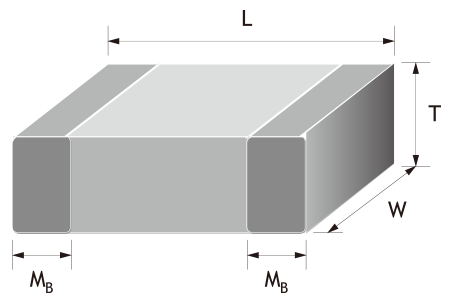
| Inch (mm) |
0402 (1005) |
0603 (1608) |
0805 (2012) |
| L |
1.00±0.05 |
1.60+0.15/-0.10 |
2.00±0.20 |
| W |
0.50±0.05 |
0.80+0.15/-0.10 |
1.25±0.20 |
| T |
0.50±0.05 |
0.80+0.15/-0.10 |
0.60~1.25±0.20 |
| MB |
0.25+0.05/-0.10 |
0.40±0.15 |
0.50±0.20 |
| Inch (mm) |
1206 (3216) |
1210 (3225) |
1808 (4520) |
1812 (4532) |
| L |
3.20±0.20 |
3.20±0.40 |
4.50±0.40 |
4.50±0.40 |
| W |
1.60±0.20 |
2.50±0.30 |
2.03±0.25 |
3.20±0.30 |
| T |
0.80~1.60+0.30/-0.10 |
0.95~2.5±0.30 |
1.25~2.0±0.20 |
1.25~2.50±0.30 |
| MB |
0.60±0.20 |
0.75±0.25 |
0.75±0.25 |
0.75±0.25 |
Unit: mm
Capacitance Range
| Size |
NPO |
X5R |
| 10/25V |
50V |
100V |
6.3V |
10V |
16V |
| 0402 |
Min. |
0.5pF |
0.5pF |
0.5pF |
0.22μF |
0.056μF |
0.027μF |
| Max. |
470pF |
220pF |
150pF |
1.0μF |
0.1μF |
0.1μF |
| 0603 |
Min. |
0.5pF |
0.5pF |
0.5pF |
0.86μF |
0.33μF |
0.33μF |
| Max. |
3300pF |
1000pF |
560pF |
2.2μF |
1.0μF |
1.0μF |
| 0805 |
Min. |
0.5pF |
0.5pF |
0.5pF |
2.2μF |
2.2μF |
2.2μF |
| Max. |
0.012μF |
4700pF |
3900pF |
10μF |
4.7μF |
4.7μF |
| 1206 |
Min. |
1.5pF |
1.5pF |
1.5pF |
4.7μF |
2.2μF |
1.5μF |
| Max. |
0.039μF |
0.015μF |
8200pF |
22μF |
10μF |
4.7μF |
| 1210 |
Min. |
22pF |
22pF |
10pF |
--- |
2.2μF |
2.2μF |
| Max. |
0.015μF |
0.015μF |
0.015μF |
--- |
10μF |
10μF |
| 1812 |
Min. |
--- |
1000pF |
10pF |
--- |
--- |
--- |
| Max. |
--- |
0.033μF |
0.033μF |
--- |
--- |
--- |
| Size |
X7R |
Y5V |
| 10/16V |
25V |
50V |
100V |
10V |
16/25V |
50V |
100V |
| 0402 |
Min. |
0.012μF |
5600pF |
100pF |
--- |
0.15μF |
0.01μF |
0.01μF |
--- |
| Max. |
0.1μF |
0.022μF |
0.01μF |
--- |
0.47μF |
0.1μF |
0.033μF |
--- |
| 0603 |
Min. |
0.082μF |
0.033μF |
100pF |
100pF |
0.68μF |
0.22μF |
0.01μF |
--- |
| Max. |
0.22μF |
0.1μF |
0.1μF |
0.01μF |
1μF |
1μF |
0.15μF |
--- |
| 0805 |
Min. |
0.39μF |
0.082μF |
100pF |
100pF |
--- |
0.47μF |
0.01μF |
0.01μF |
| Max. |
1μF |
1μF |
0.22μF |
0.1μF |
--- |
1μF |
0.47μF |
0.15μF |
| 1206 |
Min. |
0.27μF |
150pF |
150pF |
150pF |
--- |
0.01μF |
0.01μF |
0.01μF |
| Max. |
4.7μF |
1μF |
1μF |
0.22μF |
--- |
1μF |
1μF |
0.22μF |
| 1210 |
Min. |
--- |
0.33μF |
1000pF |
1000pF |
--- |
--- |
0.1μF |
0.01μF |
| Max. |
--- |
1μF |
1μF |
0.56μF |
--- |
--- |
1μF |
0.33μF |
| 1812 |
Min. |
--- |
0.68μF |
1000pF |
1000pF |
--- |
10μF |
1μF |
--- |
| Max. |
--- |
1μF |
1μF |
1μF |
--- |
47μF |
6.8μF |
--- |
Capacitance Range(High Voltage)
| Size |
NPO |
| 200V |
250V |
500V |
1000V |
2000V |
3000V |
| 0603 |
Min. |
22pF |
22pF |
--- |
--- |
--- |
--- |
| Max. |
100pF |
100pF |
--- |
--- |
--- |
--- |
| 0805 |
Min. |
0.5pF |
0.5pF |
0.5pF |
--- |
--- |
--- |
| Max. |
820pF |
390pF |
390pF |
--- |
--- |
--- |
| 1206 |
Min. |
1.5pF |
1.5pF |
1.5pF |
1.5pF |
1.5pF |
--- |
| Max. |
2200pF |
1000pF |
1000pF |
470pF |
220pF |
--- |
| 1210 |
Min. |
10pF |
10pF |
10pF |
10pF |
10pF |
--- |
| Max. |
3900pF |
2700pF |
1800pF |
470pF |
220pF |
--- |
| 1808 |
Min. |
--- |
--- |
--- |
2.2pF |
2.2pF |
2.2pF |
| Max. |
--- |
--- |
--- |
1000pF |
680pF |
270pF |
| 1812 |
Min. |
10pF |
10pF |
10pF |
10pF |
10pF |
10pF |
| Max. |
6800pF |
3300pF |
3300pF |
1500pF |
1000pF |
470pF |
| Size |
X7R |
Y5V |
| 200V |
250V |
500V |
1000V |
2000V |
3000V |
200V |
250V |
| 0603 |
Min. |
--- |
--- |
--- |
--- |
--- |
--- |
--- |
--- |
| Max. |
--- |
--- |
--- |
--- |
--- |
--- |
--- |
--- |
| 0805 |
Min. |
100pF |
100pF |
100pF |
--- |
--- |
--- |
0.01μF |
0.01μF |
| Max. |
0.022μF |
0.022μF |
2700pF |
--- |
--- |
--- |
0.068μF |
0.068μF |
| 1206 |
Min. |
150pF |
150pF |
150pF |
150pF |
150pF |
150pF |
0.01μF |
0.01μF |
| Max. |
0.1μF |
0.1μF |
0.033μF |
4700pF |
1500pF |
1000pF |
0.15μF |
0.15μF |
| 1210 |
Min. |
1000pF |
1000pF |
1000pF |
1000pF |
--- |
--- |
0.01μF |
0.01μF |
| Max. |
0.47μF |
0.47μF |
0.056μF |
0.01μF |
--- |
--- |
0.15μF |
0.15μF |
| 1808 |
Min. |
--- |
--- |
--- |
150pF |
150pF |
150pF |
--- |
--- |
| Max. |
--- |
--- |
--- |
0.01μF |
2200pF |
1000pF |
--- |
--- |
| 1812 |
Min. |
1000pF |
1000pF |
1000pF |
270pF |
270pF |
680pF |
0.01μF |
0.01μF |
| Max. |
0.47μF |
0.47μF |
0.1μF |
0.015μF |
4700pF |
820pF |
0.68μF |
0.68μF |
Typical Characteristics Chart